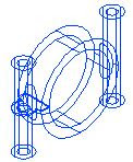
Sunday, January 31, 2010

Views with Hidden Lines Removed

There are 3 options that do not display lines that would be considered hidden
3D Hidden
Appears as a wireframe silhouette 轮廓 of a 3D model

Conceptual
Apply color to faces of models and hide hidden lines
Uses a transition between colors

Realistic
Displays 3D models in the colors assigned
Displays materials if they are attached


Wireframe View


2D Wireframe 3D Wireframe

3D Wireframe visual style offers properties and settings that are not available in the 2D Wireframe visual style

Type of Views

Produce different types of views depending on the intended audience

Top-left: Conceptual Top-right: Realistic
Lower-left: Wireframe Lower-right: 3D Hidden

Using visual styles to generate views based on geometry view types: Wireframe, Hidden, or Shaded

Thursday, January 28, 2010

Creating Drawings from 3D Models

Visualization, interference checking, and mass property information are a few of the benefits of creating designs with 3D models

As design in 3D, still need to create 2D documents of models
Using layouts can create all the views necessary to document the models

Generating 2D/3D Sections

Home tab > Section panel > Create Block


Generate 2D or 3D sections and elevations of model

2D section has been updated to reflect the new section plane shape and settings

Section Planes States

Section Plane

The section plane extends infinitely

Section Boundary

The section plane object contains side planes and a back plane extending infinitely, and can section a model from all four sides

Section Volume

The section plane contains side planes, a back plane, and top and bottom planes
The model can be sectioned on six sides

Section Plane Options


  1. Standard grips for editing the endpoint location of the section plane
  2. Click to display shortcut menu
  3. Midpoint grip for changing the location of the section plane
  4. Flip the view direction of the section plane

Manipulating Section Planes


  1. The original 3D model with live sectioning enabled
  2. A 3D model of the assembly based on the section plane
  3. A 2D cross section based on the section plane

Section Plane


Use section planes to view internal sections of 3D models

Create 2D cross sections of models
Create 3D cross-sectional models
Generate 2D geometry containing mass property information

Use mass property information in strength and area calculations
Determining items such as safety factors or material costs

Section command

A simple section is a non-associative 2D representation of 3D model at a given plane that define

Two different section results are shown for the same solid model
1st section shows the section cut at the lower end of the model
2nd section shows the results when placing a section at the midpoint of the model

Flatshot

Create different 2D views of the 3D model

The ability to create accurate 2D data efficiently is significant since most of today's industry still relies on 2D data as the primary means of communication between designers and manufacturers

1. Set the viewing orientation to any orthographic view (Top, Bottom, Front, Back, Right, Left)
2. Section Plane > Flatshot

Wednesday, January 27, 2010

Flattened Views

A view created from a 3D model in which objects are projected in their current position, relative to the view, onto a plane that is parallel to the current view

Flattened views can be from any angle and are not limited to standard orthographic projections

Section a Solid Model

While designing in 3D offers significant advantages, designs may still have to be displayed in a 2D format for manufacturing

View the information in 3D or 2D form
Generate 2D cross sections based on the planes define that can be used to generate mass property information or create 2D drawing views

Tuesday, January 26, 2010

Creating a Computer Mouse

Take a simple mesh box primitive and manipulate it into an ergonomic 人体工程学 design for a computer mouse

1. First set the subobject filter to Edge:
  • Mesh Modeling tab > Subobject panel > Edge
  • This enables the edges to be selected when perform the subobject selection steps

2. To select the subobject edges which will define the raised area for the mouse buttons:
  • Press and hold CTRL
  • Click each of the four subobject edges
3. To move the selected edges using the 3DGizmo:
  • Click the Z axis on the 3D-Gizmo
  • Position the edges approximately as shown
  • Click to complete the move
4. To smooth the basic shape of the mouse object:
  • Mesh Modeling tab > Mesh panel > Smooth More
  • Repeat the Smooth More command twice
5. Next, raise the center ridge 脊状突起 for the mouse wheel opening:
  • Press ESC to clear any existing selections
  • Press and hold CTRL
  • Select the two subobject edges
6. Move the selected edges using the 3D-Gizmo:
  • Click the Z axis
  • Position the edges approximately as shown
  • Click to complete the move
7. Now, use the 3D-Gizmo to widen the mouse uniformly on each side towards the front:
  • Press ESC
  • Press and hold CTRL
  • Select the subobject edges as shown in the first of the following illustrations
  • Rotate the view 90 degrees
  • Select the corresponding subobject edges on the other side as shown in the bottom illustration
8. Switch the 3D-Gizmo to scale mode:
  • Place your cursor at the origin of the 3DGizmo
  • Right-click. Click Scale
9. Next, relocate the 3D-Gizmo midway between the edges:
  • Place your cursor at the origin of the 3DGizmo
  • Right-click and click Relocate Gizmo
  • SHIFT+ Right-click. Click Mid Between 2 Points

10. Finish locating the 3D-Gizmo:
  • Click point 1
  • Click point 2
  • The 3D-Gizmo is located at the center of the object for a uniform scale
11. Next, scale the selected edges equally:
  • On the 3D-Gizmo, click the X axis
  • Drag to widen the object at the selected edges
  • Click to place the new width
  • Press ESC

12. View your model from different viewpoints
The object in the following illustration is shown in the NW Isometric view

13. Next, to define a flat bottom for the mouse and add a crease to the bottom faces:
  • Using the ViewCube, display the Left view
  • Mesh Modeling tab > Subobject panel > Face
  • Mesh panel > Mesh Edit panel > Add Crease
  • Window select the bottom faces. Press ENTER
  • Press ENTER again to accept the Always option
14. Rotate the object and view the flat underside

15. Now that the shape is defined for the mouse, convert the object to a solid so that additional
features can be added:
  • Modeling tab > Convert Mesh panel > Smooth, Optimized
  • Mesh Modeling tab > Convert Mesh panel > Convert to Solid
  • Select the object and press ENTER