Monday, November 30, 2009

Lofted


Create models of free form shapes
Models that change from one shape to another
Change the size and orientation in 3D space

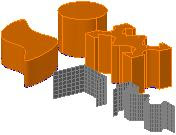
  1. Geometry consists of two closed loop cross sections, one a circle and the other a polyline; and three open loop cross sections, two lines and a spline
  2. Surface model created by selecting the open loop geometry as the cross sections and the closed loop geometry as guides
  3. Solid model created by selecting the closed loop geometry as the cross sections and the open loop geometry as guides
  4. Solid model created by selecting the closed loop geometry as the cross sections and the spline on the right as a path
  5. Solid model created by only selecting the closed loop geometry and selecting the Ruled loft setting
  6. Solid model created by only selecting the closed loop geometry and selecting the Smooth Fit loft setting
  7. Solid model created by only selecting the closed loop geometry and selecting the Draft Angles loft setting with a 90 degree start angle and end angle for 50% of the distance

Swept


Create a model that has a more free form or compound shape

A shape that is not solely linear 唯一线状 and does not have a single axis it can revolve around
Having planar profile geometry follow the path defined by another piece of geometry
Sweep path can be an open or closed loop

Solid model created by sweeping the square along the helical path shown to the right of the model
Square profile swept along the same straight line. Right model had an angle value set for the Twist suboption
Solid model created after sweeping the closed loop profile along the spline path
Surface model was created because the profile was modified to be individual objects

Revolved


Create an arcing or circular 3D model from a 2D profile


Create geometry that traverses in all directions through space

Models that show material that is bent, rolled, or cast in an arc or circular shape

1. Surface mode for individual objects
2. Solid model created after defining the axis and revolving 360 degrees
3. Specifying 180 degrees instead of 360 degrees
4. Specifying a starting angle other than 0 and not revolving a full 360 degrees

Extruded

A model is created a specified distance and direction between the original planar profile and a projection of that profile

D
ELOBJ
1: Original profile geometry automatically deleted
0: Original profile geometry automatically maintained

Different models were created from variations of the same profile shape and command options

1. Surface model was created because the closed loop was not a single object
2. Solid model created after specifying a height and following the default workflow
3. Using the Direction suboption and specifying a direction between two points
4. Using the Path suboption and selecting the 3D spline shown
5. Specifying a positive Taper Angle and a height

Multiple Segmented Solid


Multiple segmented solid of straight and arc segments

Open loops profiles: a single object does not return to its starting point and close itself

1. Height
2. Width
3. Justify (left, center, right)

Planar surface


Create profile geometry in a flat plane anywhere in space

Closed loop profiles: a single object that does return to its starting point

Models from 2D Profiles

Using common drawing geometry as the input for creating surface or solid models

A complex solid model created from different cross sections of geometry

Sunday, November 29, 2009

Using Free-Form Design

1. Creating mesh objects or solids

2. Use Mesh, Mesh Edit, and Subobject tools to edit the meshes or solids as required to define the shape

3. Continue to sculpt and refine the design

4. Convert the mesh objects to solids or surfaces to use the additional solid editing tools or applications as required

Saturday, November 28, 2009

Create Free-Form Design


Creating free-form designs is a process that involves different methods and approaches

  1. Created the geometry
  2. Use free-form design tools to digitally sculpt the object into the desired shape
  3. Manually sculpt clay by pulling and stretching various portions or by applying creases along certain edges
  4. Convert the objects to solids or surfaces

Free-Form Sculpting


Free-form modeling is used to create an organic looking structure from a simple box primitive

Free-from design techniques to show a concept of a scooter

Free-Form Design

More prevalent uses of organic free-from shapes

Being used in all design disciplines and industries from automotive to architectural

Free-form design that result in sculpted surfaces

Acquiring Points in 3D Space


Experience problems with displaying objects, snapping to objects, or using object tracking while a 3D visual style is active, switch to the 2D Wireframe visual style and then switch back to a 3D visual style

Dynamic UCS


UCS Icon Display


Defining UCS


Change of Coordinate System

The different geometry was drawn on the different faces of the models by changing to a user coordinate system

The process of creating a 3D model can be made much simpler when break down model into smaller flat sections within the WCS

Cartesian Coordinate System

Create geometry in 3D, you will need to reorient the coordinate system to create and modify the geometry

Shade mode Wireframe mode

Cartesian coordinate system is composed of three axes (X, Y, and Z) at 90° to each other
These intersecting axes define the origin point for the coordinate system and three flat planes (XY, XZ, YZ)
1. XY Plane
2. YZ Plane
3. XZ Plane

Guideline for Mesh Surface

  • Before the creation of new mesh surfaces, other objects must be created to serve as their boundaries
  • Legacy surfaces can be converted into mesh surfaces
  • Use the Thicken command with surfaces. Do not confuse it with the Thickness command.
  • Use SURFTAB1 and SURFTAB2 system variables to control the initial mesh density prior to creating the mesh surfaces

Creating Ruled Surface Mesh

1. Create two bounding objects in different Z planes using lines, polylines, arcs, or splines

2. Mesh Modeling tab > Primitives panel > Modeling, Meshes, Ruled Surface

3. Select the first bounding object

4. Select the second bounding object
The ruled surface is created

5. Render tab > Visual Styles panel > Conceptual

6. Select the object. In the Quick Properties panel. Set the Smoothness to Level 2

7. The ruled mesh surface is complete

Create Mesh Box

1. Mesh Modeling tab > Primitives panel > Mesh Box

2. Render tab > Edge Effects panel > Isolines

3. Specify the location of opposite corners for the box base

4. Click and drag to define the height of the box or enter the height of the box

5. The mesh box in the wireframe visual style is completed

6. Render panel > Visual Styles panel > Conceptual

7. The mesh box in the conceptual visual style is completed

8. Select the box. In the Quick Properties panel, set the Smoothness to Level 2

9. The smoothed mesh box is completed