Monday, May 31, 2010

Render Window

After render a scene, the output is either displayed directly in the current viewport or in the Render window
If want to generate a file from a rendering, the rendering must be done in the Render window and not the viewport
Image pane: displays the current render in progress
Statistics pane: displays the information about the selected image in the History pane
History pane: displays the most recent renderings of the current drawing that have been done in the Render window

Render Presets


Draft: blocky-looking 块状的 render due to the low sampling, but is very fast and can provide a rough idea of what the lights in the scene are doing
Low: coarse-looking 粗糙的 render due to the low sampling, but is fast and can give a quick idea of what lights and shadows look like in a scene
Medium: good render due to the sampling and ray-trace settings
  • appear a little blurry along edges
  • a good way to test a scene for lighting and shadows before the final output
High: slightly higher quality rendering than the Medium preset
Presentation: sharply detailed renders due to the high sampling and ray-trace settings

Rendering Environment

The rendering environment consists of many user interfaces and settings that can affect shadows, materials, lights, and other aspects of rendering

Sunday, May 30, 2010

Geographic Location - Sun Properties


Only edit the geographic location settings in the Geographic Location dialog box

Rendered Shadow Details


Type: type of shadows to generate from the light that is emitted from the sun
Samples: number of samples to take on the solar disk (Soft or LIGHTINGUNITS set to 1 or 2)
Softness: control the appearance of the shadow edges

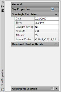
Sun Angle Calculator


Date: calendar date via a calendar control
Time: time of day in 15-minute increments
Daylight Savings: on and off, and determines whether changing the date affects the time
Azimuth: angle of the sun due north clockwise along the horizon
Altitude: angle of the sun vertically from the horizon
Source Vector: source vector of the sun, indicating the direction of the light it is emitting

Sky Properties - Sun Properties

Only available when you are using a photometric lighting workflow
The LIGHTINGUNITS system variable must be set to 1 or 2 for these options to be available
Status: Off, Sky Background, or Sky Background and Illumination
Intensity Factor: magnify the effect of the sky light
Haze: value between 0 - 15 to adjust the atmospheric scattering 大气层的散射 effects
Height: absolute position of the ground plane relative to world zero
Blur: control the amount of blurring that occurs between the ground plane and sky
Ground Color: color for the ground plane
Night Color: color for the night sky
Aerial Perspective: on or off
Visibility Distance: distance at which 10% haze occlusion 薄雾吸留 will result
Disk Scale: scale of the sun disk
Glow Intensity: adjust the intensity of the sun glow
Disk Intensity: adjust the intensity of the sun disk

Sun Properties


Render tab > Sun & Location panel > Sun Properties


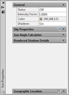
General
Status: When on, the sun is used to calculate shadows
Intensity Factor: brightness of the sun
Color: light color that the sun emits
Shadows: Selects whether shadows are calculated for the light that the sun casts

Geographic Location Dialog Box


Latitude & Longitude: location using coordinate values or time zone
Use Map: opens a map to click a location anywhere on the globe
Coordinates and elevation: where the geographic marker is placed
North Direction: angle from 0 for the north direction (positive Y direction)
Up direction: up direction is the positive Z-axis (0,0,+1)

Location Picker Dialog Box

Map: select the scene location
Region: region where the scene is located
Nearest City: nearest big city to the scene
Time Zone: time zone in which the scene takes place
Nearest Big City: snap to the nearest big city

Geographic Location


Render tab > Sun & Location panel > Set Location

Define the geographic location to calculate the proper position of the shadows
Northern Location

Southern Location

The Render tab on the ribbon is the easiest way to access the sun's settings

  1. Default Lighting: turned off when rendering to prevent affecting sunlight and shadows
  2. Sun Properties: palette on and off
  3. Sun Status: on and off
  4. Location: geographic location of the scene and the north direction of the model
  5. Sun Date: day of the year for calculating sun position
  6. Sun Time: time of day for calculating sun position

Sun

Simulate sunlight based on a geographical location, time of day, and day of the year
Determine how sunlight might appear on the outside or inside of a building

The sun is used to simulate shadow positions on a proposed home design

The sun is completely invisible in the drawing window and has no special graphic can select it in the scene

Create New Material

The changes make to material properties on the Tool Properties dialog box are not automatically applied to objects using that material

Must reapply the material from the tool palette to the appropriate objects

Create New Material

  1. Material Palette > Create New Material > Name > Description > OK
  2. Material Editor > Type > Select Material Type
  3. Template list > Select Material template (Metal, Fabric)
  4. Adjust material properties (texture, opacity, bump maps)
  5. Apply Material > Select object
  6. Render the scene

Texture Maps Search Path

Many of the predefined materials use texture maps as part of their material definition

Can add paths of locations that contain custom texture maps

Saturday, May 29, 2010

Material Offset & Preview Panel


Preview and adjust the offset and rotation values of the material

Material Scaling & Tiling


Adjust the scale and tiling properties for the selected material

Advanced Lighting Overrides


Only available when the Material Type is set to Realistic or Realistic Metal
Change the way a material is rendered when it is lit by indirect illumination

Friday, May 28, 2010

Maps Panel

Use the Maps panel to select and adjust properties for Diffuse maps, Opacity maps, and Bump maps

To apply a texture map, such as a wood grain pattern, click the Select Image icon under Diffuse Map and browse for the texture

The default path is C:\ProgramData\Autodesk\AutoCAD 2010\R18.0\enu\Textures\.

Material Editor


When creating a new material, select a material from the Template list as a starting point
These selections have preset values associated with the Shininess, Refraction Index, Translucency, Self-Illumination, and Opacity properties

Material Palettes

Render > 3D Palettes > Materials


Materials palette displays materials currently loaded in a drawing

The Materials palette is divided into five separate panels:
  • Material Editor
  • Maps
  • Advanced Lighting Override
  • Material Scaling & Tiling
  • Material Offset & Preview

Apply Material

Use materials on the tool palettes

A material from the tool palette is being dropped onto the floor object

Material

Create New materials
Use and edit existing materials

Applying materials to objects is a key part of rendering a scene
Convey 传达 the design intent by making objects appear more realistic

A material can control an object's color, shininess, transparency, illumination, and, in some cases, textures and surface qualities

  1. Floor: uses specific color properties as well as a texture map and a bump map to simulate a hardwood floor
  2. Table Top: uses a Diffuse color setting of nearly white (250, 250, 250) with the Shininess property set to the maximum setting, while the Opacity property is set to the minimum setting. Other settings are used as well to simulate a glass table top
  3. Chair Surface: uses color settings and texture and bump maps to simulate a leather seating surface
  4. Table Leg: uses the Metal-Polished template, the Shininess property set to 94, and a texture map. These properties combined with others simulate a chrome reflective surface
  5. Chair Platform: uses the Metal-Bushed template settings, specific color values, and a texture map. These properties combined with others simulate a dark blue metal surface

Editing Distance Light

Can only edit distant lights using the Properties palette

Select a distant light by the Light List palette and then display the Properties palette

Editing Spotlights

  1. Position Along Line: along the angle specified by the current position and target values
  2. Position: source location for the spotlight
  3. Hotspot: adjusts the angle of the hotspot
  4. Target: changes the position of the target location
  5. Target Along Line: target of the spotlight along the angle specified by the current position and target values
  6. Falloff: adjusts the angle of the falloff

Sunday, May 23, 2010

Common Light Properties


Name: Displays the name of the light in the scene
Type: Switches between point and spotlight lights
On/Off Status: Turns light on or off in the scene
Shadows: Toggles whether shadows are calculated for the light that the light casts 投射
Intensity Factor: Specifies the brightness of the light
Filter Color: Specifies the color light that the light emits

The three main types of lights, Point, Spotlight, and Distant light, share some common properties
Changing these properties has the same effect regardless of the type of light

Lights in Model Palette


Distant lights do not have glyphs, so it is not possible to edit them in the scene with grips
The only way to select them is to use the Light List

Light Glyphs


  1. Point light glyph: Point lights appear in a scene as a spherical glyph with crossing lines through the center
  2. Spotlight glyph: Spotlights appear in a scene as a glyph that looks like a flashlight

Turning Off Default Lighting Mode


Turn Off The Default Lighting to disable default lighting and enable the use of user lights and the sun

Light Panel


  1. Create a Point/Spot light: Starts the Light command with the Point or Spot option
  2. Shadows: Controls whether Full, Ground or No shadows are displayed
  3. Default Lighting Mode: Turns default lighting on and off. Default lighting must be turned off before you can use lights and the sun when rendering
  4. Brightness Slider: Controls the brightness of all the lights in the scene by a given factor; typically used with default lighting
  5. Contrast Slider: Controls the contrast of all the lights in the scene by a given factor; typically used with default lighting
  6. Midtones Slider: Controls the midtone values for exterior scenes that are lit by the sun. This slider is only available when the LIGHTINGUNITS system variable is set to 1 or 2
  7. Light Glyph Display: Turns on and off the display of the glyphs in the drawing that represent the location of point lights and spotlights
  8. Units: Controls whether Generic units, American units (generic) or SI units (photometric) lights are used
  9. Lights in Model: Displays the Lights in Model palette on which you can select lights in the scene and display their properties on the Properties palette

Distance Light

Emits 射出 light uniformly in a single direction based on a From and a To vector

Distant lights are good for filling a scene with an even amount of light, like Sun Light

Spot Light

Emits light from a source location to a target based on the shape of a cone

Outer Cone: define when the light starts to fall off
Inner Cone: determines the hot spot of the light

Spot lights are good for emulating 仿效 sources of light such as floodlights and track lighting

Saturday, May 22, 2010

Point Light

Emits light in all directions from its specified location

Point lights are good for emulating sources of light such as light bulbs, lanterns, and candles

Lighting

Lighting is used to set a specific mood in a scene or draw attention to a specific area or detail
Day: warm and bright

Night: warm and inviting
Lighting in a scene must be done with the right balance of lights and shadows

It is best to start with a few lights and adjust their properties to produce the desired look before adding more lights
Lights cast shadows, so to add too many can confuse someone when they are looking at a rendered scene

When default lighting is enabled, there are two distant light sources available for your scenes that emit light onto all visible faces
Default light does not cast shadows, so usually not used when rendering a scene with materials

Export Visual Style

The easiest way to make the style available in another drawing is to export it to a tool palette

Export Visual Style by Visual Style Manager
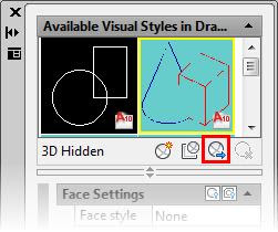
Highlight the desired visual style and click the Export the Selected Visual Style to the Tool Palette button

Drag Export to Tool Palette
The selected visual style has been dragged to the active tool palette

The exported Visual Style becomes completely independent

Friday, May 21, 2010

Visual Style Override

Create temporary visual style overrides:
  1. Changing a visual style's properties on the Render tab
  2. Visual Styles and Edge Effects panels
Visual Style Panel
1. Visual Style Manager
2. Visual Style
3. X-Ray Effect
4. Opacity
5. Face Color Mode
6. Face Style
7. Lighting Quality
8. Performance Tuner

Edge Effects Panel
1. Edges
2. Edge Overhang toggle / Edge Overhang slider
3. Edge Jitter toggle / Edge Jitter slider
4. Silhouette Edge toggle / Silhouette Edge Width slider
5. Obscured Edges toggle / Obscured Edges Color pull-down
6. Intersection Edges toggle / Edge Intersection Color pull-down
7. Edge Color

Temporary overrides made here are not saved automatically