

- Can 3D print solid models or watertight meshes only (Watertight: a closed model with no openings or loosely joined edges)
- AutoCAD does not support 3D printing of colors or materials
- 3D printed parts have limitations on minimum wall and shell thickness (Check with vendor)
- Determine the correct amount of clearance required for moving parts (Check with vendor)
- If a complex model gives errors during 3D Print, manually union the individual objects together one at a time, and retry 3D Print
- Preview window will help to determine if the model will print correctly. Expand the 3D Printing Pane preview to ensure all selected objects are present
Sunday, June 6, 2010
Guidelines for 3D Printing
Send 3D Print to Service
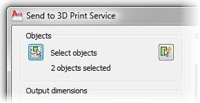
1. Output tab > 3D Print panel > Send to 3D Print Service

2. 3D Printing dialog box > Continue

3. Select the objects to send. They must be solids or watertight (closed) meshes

4. Choose to add more objects to the selection set or use the Quick Select panel to create a selection set filter
5. Change the scale or the output dimensions of the model

6. Use the preview window to verify what will be printed ( not reflect the edit changes)

7. Choose a location and file name for the ST file

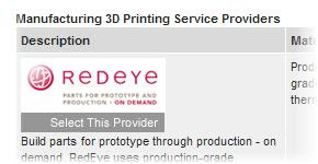
8. Browser will open and link to the Autodesk 3D Printing web page. Review all vendors and select one that meets the needs
3D Printing in Industrial
3D Printing can be used in many imaginative 想象的 ways:
Assemblies
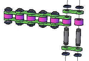
For manufacturing applications, in one run can build a working model with multiple moving parts
All the parts can be created at one time using one STL file
No assembly is required
Tooling
Create a mold using 3D printing
Architecture
Create a complete mockup 实体模型 of a building with fixtures, doors, and even furniture if desired
Create a separate roof that can be removed
How 3D Printing Works
When convert the 3D model into an STL file, it digitally slice it into many thin section views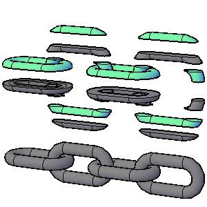
The STL machine creates a thin layer of plastic that is dimensionally accurate in shape and size to each section view
It creates each layer in the proper order and permanently attaches it to the previous layer
Several components of an assembly can be made in place at the same time
Multiple pieces can be created in successive layers to create a moving assembly
3D Printing
Output tab > 3D Print panel > Send to 3D Print Service
3D Printing is a process that include several types of rapid prototyping technology

Stereolithography 立体平版印刷 (commonly abbreviated to STL or SLA) is the technical term for one process that enables to create plastic 3D models directly from AutoCAD composite solid or mesh models
The original file remains intact 完整无缺 and a new file is created with the extension .stl

The new file is imported into a stereolithography machine which creates the physical model
Saturday, June 5, 2010
Digital Prototype
In some cases having a physical model that can touch and examine, can provide additional insight to the design and assist in presenting that design to others
3D Printing enables to create a physical, scaled prototype of your design that is both cost effective and easy to produce
Finding errors or envisioning ergonomic 人类环境改造学的 improvements before committing to expensive production tooling can prevent costly changes
Create a Recorded Walk
1. Exercise thumbnail > Play > New Shot
2. New View / Shot Properties dialog box:
- View name: enter walk to kitchen
- View category: select Exercise
- View type: select Recorded Walk
- Transition type: select Cut to shot
- Click Start Recording
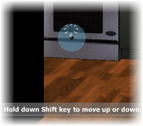
3. Use the Walk controls to create a short recording:
- Move the cursor over the door of the stove before you click
- Hold the mouse button down. Move the cursor further from the control point, will faster the movement
- Release the mouse button to stop recording
- Click Preview to review the recorded walk
- If necessary, repeat steps 2 and 3 to rerecord the Walk
- Click OK
4. Review your cinematic shot sequence
Status bar > Show Motion
Exercise thumbnail > Play
Create a Cinematic Shot
1. On the ShowMotion controls
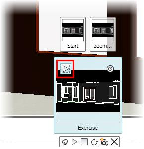
- Move your cursor over the Exercise category, Start shot
- Click Play
- Click New Shot
2. In the New View / Shot Properties dialog box
- View name: enter zoom in
- View category: select Exercise
- View type: select Cinematic
- Transition type: select Cut to shot
- Movement type: select Zoom In
- Duration: adjust the value to 4 seconds
- Distance: adjust the value to 650
- Motion: select Starting Point
- Click Preview. The preview should appear to fly through the door and look back at it
- from the inside out
- Click OK
3. Exercise category thumbnail > Play
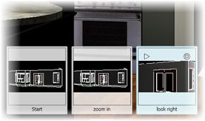
4. Show Motion toolbar > New Shot. New View / Shot Properties dialog box
View name: enter look right
View category: select Exercise
View type: select Cinematic
Transition type: select Cut to shot
Movement type: select Look
Duration: adjust the value to 6 seconds
Select Degrees right and set the value to 90
Motion: select Starting Point
Preview > The camera should turn to the right and point at the stove
Click OK
5. Exercise category thumbnail > Play
Ceate a New Shot
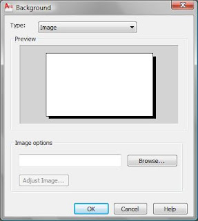
1. Move your mouse over the thumbnail labeled none, then the thumbnail labeled 1. Click Go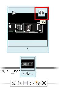
2. ShowMotion controls > New Shot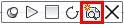
2. ShowMotion controls > New Shot
3.
Name: Start
View Category: Exercise
View type: select Still
Transition type: select Fade from black into this shot
Transition duration: 2
Duration: 3 seconds
4. Move the mouse over the thumbnails labeled Exercise, Start. Click Play
New View/Shot Properties

- View Name: Specifies the view's name
- View Category: Specifies a category for the named view
- View Type: Specifies a view type of Still, Cinematic, or Recorded Walk
- View Properties: Controls whether the animation will continue with the first view after it reaches the last one
- Transition: Defines the transition type to use
- Motion: Defines the behavior of the motion to use
- Preview: Previews the transition and motion assigned to the view
- Loop: Continuously plays back the transition and motion assigned to the view
New Shot

Using ShowMotion, can add movement and transitions to named views and captured camera positions
These animated views are called shots
There are three types of shots:
- Still: comprised 包含of single stored camera positions
- Cinematic: utilizes 利用 a single camera position with additional cinematic camera movement applied
- Recorded walk: click and drag along the path of desired animation
Thursday, June 3, 2010
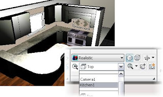
ShowMotion Presentation

Visually navigate between named views in the current drawing
Play a slideshow that will automatically cycle through all the views in a category

- Pin ShowMotion: Locks the ShowMotion control panel
- Play All: The current drawing automatically cycles through all the views in the selected category
- Stop: Stops ShowMotion
- Turn On/Off Looping: Controls whether the animation will continuously play back
- New Shot: Activates the New View / Shot Properties dialog box
- Categories: Displays a thumbnail image for each view category in the drawing
- Views: Displays the named views that are defined in the selected category
- Play: Enables to play shots and view categories
- View Go: Enables to move the camera to key positions while modifying shots or view categories
Right-click any of the view or category thumbnails

Arrange, delete, and edit the properties of the views
View Background - View Manager
View Manager > View > Background
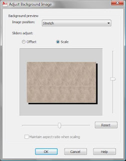
Browse...
Adjust the image's position, offset, and scale values
View Manager
Modify the view properties for custom views
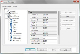
Customize view
- use the Layer Snapshot property to return layers in the view to the state they were in when clicked the Update Layers button
- associate a specific visual style with the view
- associate a live section from an existing section plane
- configure a background override (solid color, gradient, or raster image)
Activating a View
Home tab > View panel > Select a view from View list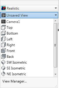
Switching between various predefined and custom views, can be easily select
Creating a Camera
1. Render tab > Camera panel > Create Camera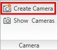
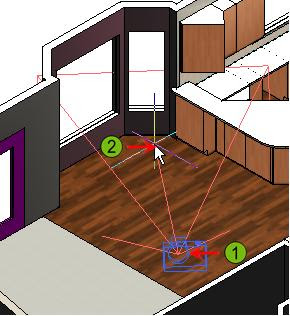
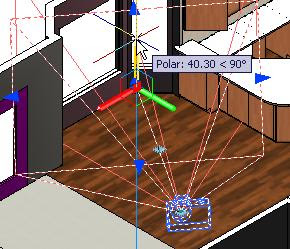
2. Click to define the camera's location (1)
Click to define the camera's target (2)
3. Enter an option for the command, for example, N for name, or press ENTER to accept the default name and options and exit the command
4. Select Camera to show grips
Drag the grips to adjust the camera or target location, as well as the Lens/FOV properties
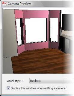
5. The Preview Window displays the camera's real-time view
Visual Style can be select from the list
Camera Command Options
Name: name for the camera (view name as well)
Location: coordinate for the camera
Height: value for the camera's height in the Z axis
Target: coordinate for the target location
Lens: value for the lens length
Clipping: Turn the front and back clipping planes on and set their offset values
View: Change the current view to the camera's view
Exit: Exit the Camera command
Camera & View
When creating camera, a view also created
Perspective: ON, a camera is created and appears as a view in the view list
Camera
Use cameras to create perspective views of the models, simulating real-world views of virtual objects

Like using a real camera, the resulting views are based on the camera's position, target, field of view, and lens properties

- Camera Location Grip: Click and drag to move camera
- Target Location Grip: Click and drag to move camera target
- Lens Length/FOV Grip: Click and drag to adjust the lens length and field of view properties
- Camera and Target Location Grip: Click and drag to move the camera and target at the same time
Create Motion Path Animation
1. Render tab > Animations panel > Animation Motion Path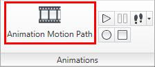
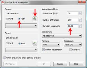

2. Camera > Path, Animation Settings > Duration (seconds): 10 > Select Path
3. Select orange spline path
4. Accept the default name Path 1 > OK > Preview
5. Animation Preview window > select different visual styles > Close the Preview window
6. Create Animation > OK > Save As dialog box: Path Animation > Save
Using Animation Paths

Using Animation Paths, can animate flying through a model by attaching a camera to a path and animating the camera or target along the path
The animation is stored as a movie and can be played back by any computer that supports the WMV, AVI, MOV, or MPG formats
Recording an Animation
The animation controls Play, Record, Pause, and Save are only available while the 3D walk or 3D fly commands are active
1. Start the 3D walk or 3D fly

2. Render tab > Animation panel > Record

3. Begin navigating through the model using standard walk or fly navigation methods

4. Click Save Animation
5. Save As dialog box > Enter File name > Save

Higher frame rates generate smoother animations
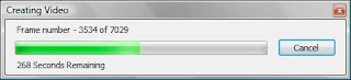
6. To see the animation, Tool tab > Animation panel > Play

Walk and Fly Settings

- Step Size: Enter a value for the step size (larger value results in faster navigation)
- Steps Per Second: Enter a number between 1 and 30
Position Locator
Position Locator palette is displayed for 3D Walk & 3D Fly
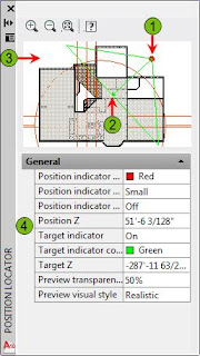
- Position indicator: Click and drag to rotate the position around the target
- Target indicator: Click and drag to adjust target
- Preview Window: Shows objects in your drawing
- Properties: Adjust the properties of the Position Locator and the preview window
Target & Cursor - 3D Walk

- Current target: Press the forward key to move towards this target
- Cursor: Click and drag to reposition the target
3D Walk & 3D Fly
3D Walk 

3D Fly 

Difference
3D walk: limited to movement on the XY plane
3D fly: move on all planes
Subscribe to:
Comments (Atom)